
- August 2026 (1)
- July 2026 (1)
- June 2026 (3)
- April 2026 (1)
- March 2026 (1)
- February 2026 (1)
- January 2026 (1)
- July 2025 (2)
- July 2024 (1)
- December 2023 (1)
- July 2023 (7)
- June 2023 (1)
How to Improve Product Performance: EMI Filter Integration
Sep 26, 2022The primary purpose of an EMI filter is, of course, to mitigate EMI. However, the integration of an EMI filter will also have an impact on many other attributes of the device. A thoughtfully designed EMI filter can improve overall product performance beyond just attenuation.
This blog will briefly review the important effects to consider, such as temperature, overload, distortion, and more.
KEY ATTRIBUTES TO CONSIDER
Rated Current: Established by max. current drawn and max. ambient temperature. Performance and magnetic properties of chokes are highly dependent on the core material. As current and temperature increase, Impedance diminishes, and the choke saturates.
In-Rush Current: Occurs when the filtered device is first turned on. Initially, peak current can be much larger than normal steady state current. If this peak is too high or lasts too long, filter components risk overheating. To ensure they can withstand current overload, off-the-shelf filters are tested per MIL-F-15733 at 140% rated current, at rated frequency, for 15 minutes.
Rated Frequency: Rated operating frequency of EMI filters is determined by the behavior of the capacitors.
Rated Voltage: A continuous voltage that establishes the voltage the EMI filter capacitors must withstand without breakdown or malfunction. Follow proper capacitor derating guidelines to ensure the filter is reliable when operated continuously at its rated voltage.
Voltage Drop: AC and DC voltage drop tests ensure that the voltage dropped across the impedances of the filter does not negatively impact the voltage seen at the load.
Voltage Overshoots and Spikes: EMI filters contain inductance in the chokes. Fast switching of dV/dt circuits results in very high amplitude overshoots and spikes, which causes stress to the insulation of the windings. This can greatly impede filter reliability.
Harmonic Distortion and Instability: Applies to filters utilized in switching power supplies. The negative input impedance of a switching power supply can oscillate in conjunction with the output impedance of the filter.
To avoid this, we use the Middlebrook Criteria, which dictates that the output impedance of the filter must be less than the reflected load impedance of the switching power supply.
Oscillation can occur if two or more filters follow each other in series. If the filters are high Q (> 2) they can detune each other.
This phenomenon shifts the cut-off frequency into the bandpass region, which reduces the input voltage and can lead to device malfunction.
Total capacitance of the cascaded could also result in higher line and harmonic currents, increasing heat in the filter.
Voltage Regulation, Clamping or Smoothing: Do not rely on EMI filters to provide voltage regulation, clamping or smoothing. Excessive distortion of the power line frequency is minimized by keeping a small value of inductive reactance.
Capacitors used to suppress differential mode (DM) noise should have reactance that is no less than 100x the filtered device’s input impedance.
SAFETY REQUIREMENTS
In addition to the characteristics and effects listed above, designers also need to keep in mind any safety requirements applicable to the filtered device. Note that filters purchased off-the-shelf items should already have mandatory safety agency approvals, but safety testing is still required for the end product.
Leakage Current: The allowable earth leakage current limit of the filtered device is based on the appliable safety standard, such as IEC 60601-1 for medical devices. For medical devices, maximum allowed is 3.5mA and minimum is 0.1mA if contact with a patient is involved. These limits dictate the values of the line-to-earth connected common-mode capacitors (Y-caps).
Leakage current is calculated with the formula:
Leakage Current = V * 2πF * C * 1.2μA
Where:
- V is maximum rated mains supply voltage;
- F is 50 or 60Hz;
- C is in μF;
- 2 represents a 20% capacitor tolerance.
If common-mode (CM) emissions are a problem and leakage current requirements prevent adding more Y-cap capacitance, adding more CM choke inductance may be the solution. This is achieved either by increasing the value of the CM-choke or adding another CM-choke to the EMI filter design.
Component Ratings: Safety standards such as IEC 60384-14 describe the rating requirements for X-caps (line-to-neutral, differential-mode) and Y-caps. Both types carry mains voltages continuously and must be specially rated to do so. Failure of X- or Y-caps can lead to fire and shock hazards.
X- and Y-caps have different classes (eg. X1, X2, Y1, Y2) with different voltages and pulse ratings. The application and type of insulation will determine which class to use. Failing to select the proper class is a common mistake in EMI filter design, so make sure you know your requirements and choose accordingly.
Dielectric Withstand: Dielectric withstand tests, aka high potential or “hi-pot” tests, ensure that the end-product can perform properly under high voltage. There are two different types of hi-pot test.
One is performed as a type test on prototypes during product development and safety agency evaluation, while the second is applied to 100% of production units. These tests are successful if no breakdown or flashover occurs.
Insulation Resistance (IR): A quality control check in which an applied voltage is used to determine the resistance of filter components such as wiring, inductors and capacitors. Low IR indicates a problem that will worsen over time. Careful filter component layout and selection will prevent low IR values.
Temperature Rise: This check falls under both safety and reliability for an EMI filter. During safety agency approval testing, both the filter and end product are tested at maximum worst case loading conditions as expected in service.
Applied voltage is set at rated voltage plus 10%, and the end product is configured to produce its maximum load. It’s good practice to apply 20% margin on top of maximum load to cover all bases.
Thermocouples are placed on components. Temperature is determined once it has stabilized. If temperatures are found to exceed component specifications, they should be replaced, as a filter that runs too hot will have a shorter lifespan.
To sum up, there are countless factors that should go into determining your EMI filter design, as it can have a huge impact on product performance.
If you have any questions about any of this information or need help designing your own EMI filter, reach out to Ohmite.
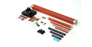
Guide to Power Resistors
Power resistors are used to dissipate energy by converting it to heat. and are designed to maintain stable performance. Call now and request a quote today!
Read More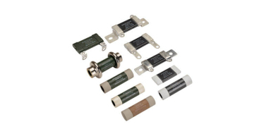
Guide to Ceramic Resistors
Ceramic Composition resistors are composed of a mixture of a finely ground insulator and conductor which is compressed into a cylindrical shape. Call now!
Read More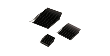
Guide to Heat Sinks
As semiconductor devices scale to smaller sizes and higher power densities, thermal management has become more challenging Call now and request a quote!
Read More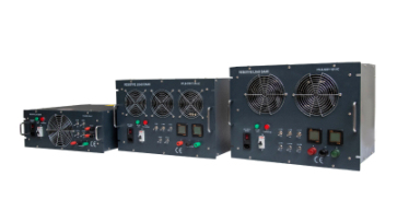
Guide to Load Banks
A load bank is a device that is intended to accurately mimic a load that a power source will see in an actual application. Call now and request a quote today!
Read More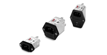
Guide to EMI Filters
To control the effects of EMI, standards are in place internationally, for commercial electronics, aerospace as well as military and space applications. Call now!
Read More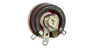
Guide to Rheostats
Rheostats, a fundamental component in electrical engineering, play a crucial role in controlling current flow and adjusting resistance in electrical circuits. Call now!
Read More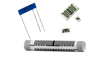
Guide to Thick Film Resistors
Thick film resistors, hailed for their versatility, durability, and wide-ranging applications, are a cornerstone of modern electronics. Call now and request a quote!
Read More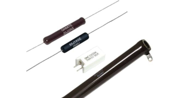
Guide to Wirewound Resistors
Thick film resistors, hailed for their versatility, durability, and wide-ranging applications, are a cornerstone of modern electronics. Call now and request a quote!
Read More
Ohms' Law Calculator
Read More
Ohm's Law 101
Ohm's Law stands as one of the fundamental principles in electrical engineering, providing a cornerstone for understanding and analyzing electrical circuits. Call now!
Read More
Energy Rating Calculator
Read More
Media Library
Read More
Technical Information
Read More
Industrial Resources
As a manufacturer of power resistors, Ohmite often creates products designed for industrial applications.
Read More
Medical Resources
As a manufacturer of power resistors, Ohmite often creates products designed for medical applications.
Read More
Transportation Resources
As a manufacturer of power resistors, Ohmite often creates products designed for transportation applications.
Read More
Military & Aerospace Resources
As a manufacturer of power resistors, Ohmite often creates products designed for military and aerospace applications.
Read More