
- August 2026 (1)
- July 2026 (1)
- June 2026 (3)
- April 2026 (1)
- March 2026 (1)
- February 2026 (1)
- January 2026 (1)
- July 2025 (2)
- July 2024 (1)
- December 2023 (1)
- July 2023 (7)
- June 2023 (1)
Heat Sinks 101: What They Are, Why We Need Them, and How to Find the Right One
Jul 21, 2022Electronic devices and circuits will generate heat in operation – this is an unavoidable fact. When components overheat, however, it can result in significant loss of performance and even major damage to the device.
The concern, therefore, is how much heat is too much and how to dissipate the excess effectively.
Heat sinks are one answer to this problem. A heat sink allows a component to dissipate heat over a larger surface area and transfer this heat to a cooling media surrounding it – usually air or a liquid coolant. This keeps the device running at an appropriately lower temperature.
Heat sinks may assist in both passive cooling and active cooling applications. Passive cooling relies on natural convection and radiation to cool a component. In active cooling, a fan or blower is required to move air through the heat sink to cool the component.
Several factors affect the performance of a heat sink, including:
- Air velocity
- Choice of heat sink material
- Design and surface treatment
- Attachment methods
- Thermal Interface Materials (TIMs)
This blog will look at the thermal performance of heat sinks and explain their features and benefits.
Basic Thermal Management Theory
First, let’s quickly review a few basic concepts.
The maximum case temperature (Tc-max), ambient air temperature (Ta), and power dissipation (Q) of the component are used to find the required thermal resistance of the heat sink.
The heat flow between the semiconductor die and ambient air can be expressed as a series of thermal resistances to heat flow (Figure 1).

Figure 1. Thermal Resistance Diagram for A Typical Electronic Component Mounting
Resistance is present from the die to the device case, from the case to the heat sink, and from the heat sink to the ambient air.
The sum of these resistances is the total thermal resistance (Rθtotal) and is expressed in units of degrees Celsius per watt (°C/W).
Heat Transfer Pathway:
IC die -> IC case -> TIM -> Heat sink -> Ambient Air
As an equation:
Rθtotal = Rθjc + Rθcs + Rθsa = (Tj – Ta) / Q
Where:
Tj: Device junction temperature (°C)
Tc: Device case temperature (°C)
Ta: Ambient temperature (°C)
Q: Device heat dissipated (watts)
Rθjc: Device junction to case thermal resistance. (Rθjc can be found on the manufacturer’s datasheet)
Rθcs: Case to heat sink thermal resistance.
- If using a TIM between case and heat sink, then Rθcs = RθTIM (Varies with material, pad or grease). RθTIM can usually be found on the manufacturer’s datasheet.
- If not using a TIM, then Rθcs is a function of surface roughness of the contact area on the heat sink and the pressure on the component.
Rθsa: Heat sink to ambient thermal resistance
Because the device junction to case thermal resistance (Rθjc) comes from the device manufacturer’s published data, and because the values are different for different devices, we usually do not include this value in the datasheet we provide.
Instead, we provide the case-to-ambient thermal resistance Rθ value, which is expressed as:
Rθ = Rθcs + Rθsa
For surface mounting devices (SMD), no TIM is needed. The heat transfer pathway is a little different (Figure 2) because the case to heat sink thermal resistance Rθcs is now the conductive thermal resistance from case to heat sink solder feet via drain-pad on PCB.
Therefore, the drain-pad thickness sets a big rule for Rθcs: the thicker the drain-pad, the smaller the Rθcs.

Figure 2. Thermal resistance diagram for a typical Surface Mount Device (SMD)
To sum up:
Rθtotal = Rθjc + Rθcs + Rθsa = (Tj – Ta) / Q
If not including the Rθjc, then:
Rθ = Rθcs + Rθsa
Once Rθ is determined, you can consult a chart typically provided by the manufacturer to find the approximate heat sink volume needed for either a natural convection heat or a forced convection heat sink at a given air velocity or a liquid cooled cold plate.
The chart provided by the manufacturer will assist in choosing a proper heat sink size based on the temperature limits for popular devices, such as D2-PAK, TO-126, TO-220, TO-247, TO-264, SOT-227 and other packages.
This chart should also provide graphs showing known values of case temperature rise ΔTc above ambient temperature Ta, and Q (watts). See Figure 3 below for an example of the graph you would find with Ohmite’s R2 Series heat sink.

Figure 3. Example graph showing heat sink’s case temperature rise above ambient temperature and thermal resistance.
Designers can simply check the graph for natural convection and determine whether the heat sink will meet the thermal design requirement.
If the device has higher power dissipation, an extrusion may be needed. In this case, a quick sizing guide may be used to find the approximate size (volume) of the heat sink to satisfy the thermal requirements.
Then, using the data sheet of available extrusions, engineers can select potential shapes and lengths that will meet or exceed this volume.
Heat Sink Materials
The material used to produce a heat sink will depend on the manufacturing method, cooling requirements, and cost analysis.
The most common heat sink materials are aluminum alloys. Aluminum is widely available, fairly strong, and tends to extrude well. Different alloys will provide different thermal conductivities and features.
Aluminum alloys 6061 and 6063 are very common, with thermal conductivity values of 166 and 201 W/m K, respectively. Aluminum alloy 1050 has a high thermal conductivity value of 229 W/m K but is mechanically soft.
Copper may also be considered, with thermal conductivity levels apx. 60% higher than that of aluminum. However, pure copper is 3x denser than aluminum – and significantly more expensive.
Ceramic (Alumina) material is growing more popular for heat sinks due to the dielectric property for high voltage circuit applications, film-printing and chip-on-heat-sink on the metalized surface, such LED lights.
Fins: Common Types and their Efficiencies
A heat sink’s fins serve to maximize the surface area over which the heat can be dissipated. There are several common types of fins:
- Extruded: Rectangular, taped and serrated, parabolic
- Bonded: Plain folded, lanced offset and wavy
- Skived: Straight fin
- Stamped: Straight, lanced, offset and folded
- Forged: Pin and blade
- CNC: Straight and pin
Fin efficiency is defined as the actual amount of heat transferred by the fin, divided by the heat transfer if the fin had infinite thermal conductivity.
In a real application, fin type is determined by the heat sink manufacturing methods, heat sink material, and cooling mode.
For example, the P series heat sink from Ohmite uses forged pin technology, meaning pins extend from its base (Figure 4).

Figure 4. Ohmite PA/PV series heat sinks use forged pin construction which allow air flow in multiple directions.
These pins make it possible for the heat sink to use either free air convectional cooling mode or forced air convectional cooling mode without the need to re-orient heat sink mounting. This allows versatility as the designer is no longer stuck forcing air in a single direction.
The flow of the coolant media is greatly impacted by the arrangement of fins on a heat sink. For example, in a flared fin heat sink (figure 5), the fins are not parallel to each other. Flaring the fins decreases flow resistance and causes more air to go through the heat sink fin channel.
Slanting the fins can keep the overall dimensions the same, but results in longer fins. Decreasing the aspect ratio of the fins increases the fins’ overall efficiency.

Component Attachments
To maximize heat transfer, there must be close contact between a sink and its selected component. Insufficient contact can increase the thermal resistance at the heat-sink-to-component interface and reduce the amount of heat flow.
At the other end of the spectrum, if a heat sink is attached too tightly, it can damage a component or cause the PCB to warp or camber.
To account for these concerns, most heat sink assemblies are designed to maintain sufficient pressure from component to heat sink and a thermally conductive interface material, such as a layer of thermal grease or a thin pad.
Popular attachment methods include thermally adhesive tape or epoxy, clips (metal spring and wire spring), fasteners, and push pins with ends that expand after installing.
When selecting an attachment, designers must consider the effective heat transfer, supporting of dynamic loads, and ease of device assembly.
For example, Ohmite offers heat sinks fitted with a patented clipping system, eliminating the use of screws-washers-nuts and holes for installation (Figure 6). No tools are required, the device can be locked in for a proper thermal connection with just one finger.
The elimination of mounting hardware also reduces assembly costs and enables uniform pressure and maximum heat transfer. This system ultimately provides an easier, more streamlined assembly process.

Figure 6: Attachment options and Ohmite’s patented clipping system
Designed for TO-126, TO-220, TO-247 and TO-264 devices, Ohmite’s C series and W series extruded heat sinks use this clipping system. The spring wire clips securely fasten a heat sink with the required contact pressure while remaining fast and easy to apply or remove.
Summary: Letting it All Sink In
Heat sinks are an essential component in electronic products, creating an efficient path for heat to be transferred away from electronic devices. A heat sink’s performance is determined by material, dimensions, surface area, fin type and air flow rate.
Each heat sink's thermal resistance should be characterized by the heat sink supplier to allow users to select the proper heat sink for an application. This selection is based upon several parameters, such as ambient air temperature, power dissipation, and cooling mode.
If the device dissipation in watts is known, the temperature rise of the die over the ambient air can be calculated by referencing thermal resistance graphs or tables. This will optimize heat sink selection so that the choice is not too small, causing burnout, or too big, wasting resources.
To begin the search for the optimal heat sink, start with Ohmite’s extensive collection. Ohmite offers an array of low-cost, configurable, scalable, and compact heat sinks to meet the needs of not only power resistors but of all active devices.
Ohmite heat sinks are designed to secure TO-126, TO-218, TO-220, TO-247, and TO- 264 packages, plus provide thermal solutions for TO-252, TO- 263, and TO-268 SMD and BGA devices.
For applications that require significant customization, a broad extrusion profile library is available to develop custom and semi-custom solutions. Get started here.
Guide to Power Resistors
Power resistors are used to dissipate energy by converting it to heat. and are designed to maintain stable performance. Call now and request a quote today!
Read More
Guide to Ceramic Resistors
Ceramic Composition resistors are composed of a mixture of a finely ground insulator and conductor which is compressed into a cylindrical shape. Call now!
Read More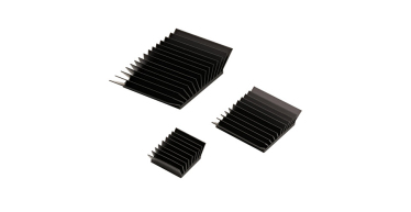
Guide to Heat Sinks
As semiconductor devices scale to smaller sizes and higher power densities, thermal management has become more challenging Call now and request a quote!
Read More
Guide to Load Banks
A load bank is a device that is intended to accurately mimic a load that a power source will see in an actual application. Call now and request a quote today!
Read More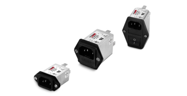
Guide to EMI Filters
To control the effects of EMI, standards are in place internationally, for commercial electronics, aerospace as well as military and space applications. Call now!
Read More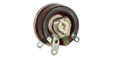
Guide to Rheostats
Rheostats, a fundamental component in electrical engineering, play a crucial role in controlling current flow and adjusting resistance in electrical circuits. Call now!
Read More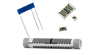
Guide to Thick Film Resistors
Thick film resistors, hailed for their versatility, durability, and wide-ranging applications, are a cornerstone of modern electronics. Call now and request a quote!
Read More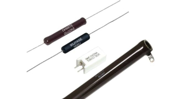
Guide to Wirewound Resistors
Thick film resistors, hailed for their versatility, durability, and wide-ranging applications, are a cornerstone of modern electronics. Call now and request a quote!
Read More
Ohms' Law Calculator
Read More
Ohm's Law 101
Ohm's Law stands as one of the fundamental principles in electrical engineering, providing a cornerstone for understanding and analyzing electrical circuits. Call now!
Read More
Energy Rating Calculator
Read More
Media Library
Read More
Technical Information
Read More
Industrial Resources
As a manufacturer of power resistors, Ohmite often creates products designed for industrial applications.
Read More
Medical Resources
As a manufacturer of power resistors, Ohmite often creates products designed for medical applications.
Read More
Transportation Resources
As a manufacturer of power resistors, Ohmite often creates products designed for transportation applications.
Read More
Military & Aerospace Resources
As a manufacturer of power resistors, Ohmite often creates products designed for military and aerospace applications.
Read More