
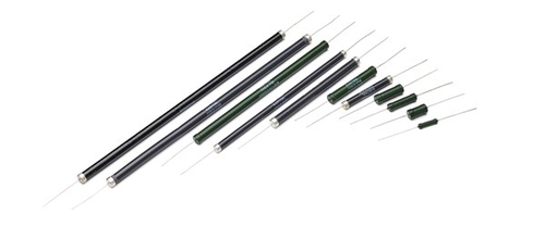
Non-inductive, high voltage, high-energy, high power axial-leaded resistors providing excellent performance where high peak power or high-energy pulses must be handled in a small size
As alternatives to hard-to-find carbon composition resistors, non-inductive high power axial-leaded resistors can be used as drop-in replacements for 1 and 2-watt sizes. Much larger sizes, up to 70 watts in a single component, are available for new or re-designs where an array of smaller resistors have been previously required.
Type AS Axial Ceramic Resistors
| Body Size | Resistance Range, Ohms | Dia. (D) Max. In. (mm) | Length (L) Max. In. (mm | Average power1, Watts | Rated peak energy2, Joules | Rated peak voltage3, Volts | Typical resistor body weight4, Gr |
| 231AS | 25-6350 | 0.2 (5.1) | 0.75 (19.1) | 1.5 | 75 | 1500 | 0.44 |
| 233AS | 6-1800 | 0.31 (7.9) | 0.75 (19.1) | 2 | 170 | 1100 | 1.2 |
| 234AS | 12-5000 | 0.31 (7.9) | 1.125 (28.6) | 3 | 275 | 2500 | 1.9 |
| 250AS | 4-1200 | 0.44 (11.1) | 0.75 (19.1) | 2.5 | 260 | 1500 | 1.9 |
| 251AS | 8-2300 | 0.44 (11.1) | 1.125 (28.6) | 3.5 | 400 | 2500 | 3 |
| 102AS | 30-9000 | 0.31 (7.9) | 2.125 (54.0) | 5 | 600 | 3000 | 3.8 |
| 252AS | 20-5800 | 0.44 (11.1) | 2.125 (54.0) | 6 | 900 | 3000 | 6 |
| 104AS | 55-18000 | 0.31 (7.9) | 4.125 (104.8) | 9 | 1200 | 9000 | 7.6 |
| 254AS | 36-12000 | 0.44 (11.1) | 4.125 (104.8) | 11 | 1800 | 9000 | 12 |
| 106AS | 90-30000 | 0.31 (7.9) | 6.125 (155.6) | 13 | 1900 | 15000 | 11.4 |
| 256AS | 60-20000 | 0.44 (11.1) | 6.125 (155.6) | 16 | 2900 | 15000 | 18 |
| 109AS | 150-48000 | 0.31 (7.9) | 9.125 (231.8) | 20 | 3000 | 25000 | 17.1 |
| 259AS | 100-32000 | 0.44 (11.1) | 9.125 (231.8) | 20 | 4600 | 25000 | 27 |
Type BA Axial Ceramic Resistors
| Body Size | Resistance Range, Ohms | Dia. (D) Max. In. (mm) | Length (L) Max. In. (mm | Average power1, Watts | Rated peak energy2, Joules | Rated peak voltage3, Volts | Typical resistor body weight4, Gr |
| 231BA | 6000-390000 | 0.2 (5.1) | 0.75 (19.1) | 1.2 | 35 | 1200 | 0.44 |
| 233BA | 1800-150000 | 0.31 (7.9) | 0.75 (19.1) | 1.6 | 80 | 900 | 1.2 |
| 234BA | 4000-300000 | 0.31 (7.9) | 1.125 (28.6) | 2.4 | 140 | 2000 | 1.9 |
| 250BA | 1000-130000 | 0.44 (11.1) | 0.75 (19.1) | 2 | 130 | 1200 | 1.9 |
| 251BA | 2000-190000 | 0.44 (11.1) | 1.125 (28.6) | 3 | 200 | 2000 | 3 |
| 102BA | 9000-700000 | 0.31 (7.9) | 2.125 (54.0) | 4 | 300 | 2400 | 3.8 |
| 252BA | 5000-450000 | 0.44 (11.1) | 2.125 (54.0) | 5 | 450 | 2400 | 6 |
| 104BA | 18000-1000000 | 0.31 (7.9) | 4.125 (104.8) | 7 | 600 | 7000 | 7.6 |
| 254BA | 12000-970000 | 0.44 (11.1) | 4.125 (104.8) | 9 | 900 | 7000 | 12 |
| 106BA | 30000-1000000 | 0.31 (7.9) | 6.125 (155.6) | 10 | 1000 | 12000 | 11.4 |
| 256BA | 20000-1000000 | 0.44 (11.1) | 6.125 (155.6) | 13 | 1500 | 12000 | 18 |
| 109BA | 48000-1000000 | 0.31 (7.9) | 9.125 (231.8) | 16 | 1500 | 20000 | 17.1 |
| 259BA | 30000-1000000 | 0.44 (11.1) | 9.125 (231.8) | 20 | 2300 | 20000 | 27 |
Type SP Axial Ceramic Resistors
| Body Size | Resistance Range, Ohms | Dia. (D) Max. In. (mm) | Length (L) Max. In. (mm | Average power1, Watts | Rated peak energy2, Joules | Rated peak voltage3, Volts | Typical resistor body weight4, Gr |
| 231SP | 1-1000 | 0.2 (5.1) | 0.75 (19.1) | 2.5 | 15 | 375 | 0.44 |
| 233SP | 1-120 | 0.31 (7.9) | 0.75 (19.1) | 7 | 20 | 375 | 1.2 |
| 234SP | 1-330 | 0.31 (7.9) | 1.125 (28.6) | 10 | 30 | 500 | 1.9 |
| 250SP | 1-150 | 0.44 (11.1) | 0.75 (19.1) | 8.5 | 20 | 375 | 1.5 |
| 251SP | 1-330 | 0.44 (11.1) | 1.125 (28.6) | 12 | 30 | 500 | 2.4 |
| 102SP | 1-700 | 0.31 (7.9) | 2.125 (54.0) | 15 | 50 | 1000 | 3.8 |
| 252SP | 1-460 | 0.44 (11.1) | 2.125 (54.0) | 18 | 75 | 1000 | 4.8 |
| 104SP | 2-1500 | 0.31 (7.9) | 4.125 (104.8) | 25 | 95 | 3600 | 7.6 |
| 254SP | 2-1000 | 0.44 (11.1) | 4.125 (104.8) | 31 | 150 | 3600 | 9.6 |
| 106SP | 3-2400 | 0.31 (7.9) | 6.125 (155.6) | 36 | 155 | 5000 | 11.4 |
| 256SP | 2-1600 | 0.44 (11.1) | 6.125 (155.6) | 45 | 240 | 5000 | 14.4 |
| 109SP | 4-3800 | 0.31 (7.9) | 9.125 (231.8) | 55 | 250 | 8800 | 17.1 |
| 259SP | 3-2500 | 0.44 (11.1) | 9.125 (231.8) | 70 | 380 | 8800 | 21.6 |
1) Rated power: De-rate linearly to 0 Watts at 230°C for Type AS and BA. De-rate linearly to 0 Watts at 350°C for Type SP.
2) Allowable peak energy/voltage will depend on the resistance value and pulse width. Energy ratings are based on pulse < 10 milliseconds. Type SP rating can be substantially greater for longer pulses. Consult us if you need more information.
3) Peak Current Ratings presume energy approaching rated peak energy values. Allowable current can be higher for low energy values. Consult us if you need more information.
4) Excludes caps/leads and coating.

| Size | Diam. D max. in (mm) | Length L max. in. (mm) |
| 231 | 0.2 (5.1) | 0.75 (19.1) |
| 233 | 0.31 (7.9) | 0.75 (19.1) |
| 234 | 0.31 (7.9) | 1.125 (28.6) |
| 250 | 0.44 (11.1) | 0.75 (19.1) |
| 251 | 0.44 (11.1) | 1.125 (28.6) |
| 102 | 0.31 (7.9) | 2.125 (54.0) |
| 252 | 0.44 (11.1) | 2.125 (54.0) |
| 104 | 0.31 (7.9) | 4.125 (104.8) |
| 254 | 0.44 (11.1) | 4.125 (104.8) |
| 106 | 0.31 (7.9) | 6.125 (155.6) |
| 256 | 0.44 (11.1) | 6.125 (155.6) |
| 109 | 0.31 (7.9) | 9.125 (231.8) |
| 259 | 0.44 (11.1) | 9.125 (231.8) |
TYPE SP
Withstands high operating temperatures resulting in high power dissipation. Maximum continuous operating temperature is specified at 350°C. This type is suitable for use in oil without an oil-resistant coating.
TYPE AS
Best suited for high energy and voltage pulse applications. Maximum continuous operating temperature is specified at 230°C. The standard dielectric coating is recommended for use in air, and the oil-resistant coating is recommended for use in oil.
Appplications:
- Soft Start/In-rush Limiters
- RC Snubber Circuits
- Spark-Gap Limiters
- Parasitic Suppression
- High Voltage Power Supplies
- Pulse Waveform
- EMI/EFI Test Circuits
- RF Dummy Load Circuits
- Capacitor Dump Circuits
TYPE BA
Best suited for high energy and voltage pulse applications where the required resistance value is above the resistance values available in Type SP and Type AS resistors. Maximum continuous operating temperature is specified at 230°C. The standard dielectric coating is recommended for use in air, and the oil-resistant coating is recommended for use in oil.
Appplications:
- DC Coupling and Filter Cap Discharge
- Voltage Balancing
- Pre-charge / Inrush Limit
- Voltage Divider
- Filter
- Snubber
- Crowbar
- Measuring
- EMI / EFI Test Circuits
- Test Loads
Physical properties (nominal)
| Type SP resistors | Type BA & AS resistors | |
|---|---|---|
| Density | 2.2 - 2.4 gm/cc | 2.2 - 2.6 gm/cc |
| Specific heat | 0.24 - 0.26 cal/gm °C | 0.23 - 0.25 cal/gm °C |
| Thermal conductivity | 0.14 - 0.16 cal/cm -°C - sec | 0.003 - 0.006 cal/cm -°C - sec |
